Monday, February 7, 2011

Project making tutorial

Here's a tutorial.
Stuff you need:
One sided copper-clad sheet
Muriatic acid
Common household hydrogen peroxide
Laser printer
Good quality magazine paper(cut for your printer-mostly 8x11 inches,thicker and shinier is better)
Plastic container that can fit the board in
Soft plastic brush
Clothes iron
Scotch brite pad or artificial steel wool (don't use real steel wool!)
Lacquer thinner
Drill and PCB drill bits
Safety goggles and rubber gloves
Software you need:
Eagle 5.11.-you can buy it here.

1.Print the following file on magazine paper using the laser printer and Eagle 5.11.Drill the holes in the indicated spots.
http://www.megaupload.com/?d=245ASNG8
Here's how to print the file:
http://www.youtube.com/watch?v=H3bXvNeINhM
This is the schematics.

2.Take the copper-clad sheet and buff it up a bit with brite pad or artificial steel wool.Then put it on the flat,sturdy heat resistant surface.
Put the printed side of the magazine paper on the board.Heat up the clothes iron and when it gets hot put it on the copper-clad sheet covered with the magazine paper.Don't allow it to move or it will get smudges.Press it and hold it like that for one minute.Don't move the iron and press really hard.
Then move the iron slowly but don't allow the paper to slide.Do that for 2-4 minutes.
Let it cool down.Put it in cold water an leave it like that soaking for about 5 minutes.Try to peel of the paper.Only the toner should remain on the sheet.If some paper remains let it soak again.If the lines are straight and there are no smudges you've done it.If not you can use lacquer thinner and paper towel to remove the toner and try again.

3.Now the etching.
Do this in a ventilated area.Pour two cups of hydrogen peroxide in the plastic container.Then pour one cup of muriatic acid (wear goggles and gloves).Don't use metal containers or stainless steel sinks.Gently and slowly wipe the board with the soft plastic brush.When the copper not covered by the toner dissolves

4.When the copper dissolves take the board and put it in water and leave it for 1-2 minutes
Now take the lacquer thinner and paper towel to get rid of the toner.
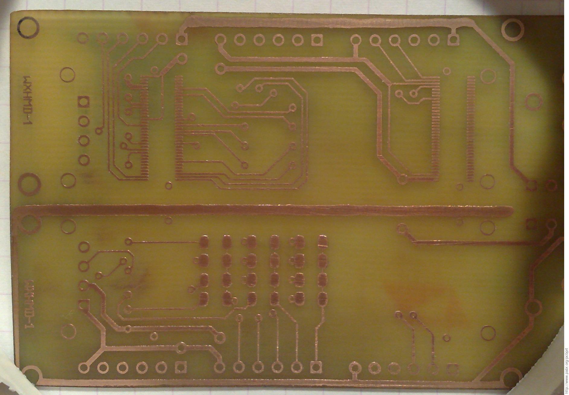
It should look like this,well of course with different areas of copper.

...to be continued...

Electronics Workbench

Electronics Workbench is a software used to simulate electrical and electronic circuits.
Its really easy to use and I would recommend it to everyone interested in electronics.

You can download it Here.
Just click the small red button saying download.
There's also a short video I made about it.

Components - Diodes

Hello.I'm back.Sorry for the delay but I've been quite busy lately.

Today I'm going to talk about diodes.Diodes are electronic components that allow current to flow in only one direction.Sounds simple right?It really is but there are several types of diodes and I'm going to talk about them.


Here's how a "standard" diode looks like.It's also called rectifying diode.


It just allows current to flow in one direction.Those wires you see sticking out of the diode are called electrodes.
The one on the left marked with the grey band is cathode(-).The other one is called anode(+).

If you connect the positive side of a battery to anode and the negative side to cathode current will flow.If you connect it the opposite way current won't flow because the diode blocks it.

(notes:

-never connect a diode to a battery without a resistor to protect it
-if you connect the diode the right way a voltage of 0,6V is required for the current to flow)

Now i'm going to tell you how diodes are made.
They're made of semiconductors(mostly silicon or germanium).


This is a diode symbol on the left and a semiconductor on the right.

(note:K is cathode,the reason it's K and not C is that in my language the word for cathode starts with K and this is the only picture i had)

As you can see the semiconductor has two parts(p and n).As you can guess "p" stands for "positive" and "n" stands for "negative".In the positive side there are more gaps(+) and in the negative side there are more electrons(-).A gap is made when an electron leaves an atom.The electrons that left the atoms in "p" side go to the "n" side.Now when you connect a battery properly electrons from the (-) side of the battery will flow to the "n" side and make it even "more negative".Then the electrons start crossing to the "p" side filling in the gaps.The (+) side takes away the electrons from the "p" side.That way the current flows.

(note:

-in the old days when electricity was discovered it was thought that the current flows from (+) to (-).Actually the current(current is directed movement of electrons) flows from (-) to (+) but changing the general perception of current flow would be too difficult so the "wrong" theory remained)


Now the other types of diodes.
Other commonly used diode is light emitting diode (aka LED).
It also allows the current to flow in one direction but when current flows through it it glows.


Here's how LEDs look like:


These are red LEDs.The other most common colors are green,blue and white.There are also double-color diodes but i will maybe talk about them later.


As shown in the picture the longer "leg" of the LED is anode.Cathode is the shorter one.Cathode is also
larger.In the top picture LED is shown from above.The side with the part cut off is the side where the cathode is.The bottom picture is shown how LED is drawn in schematics.


The next diode I'm going to talk about is called a zener diode.


As a rectifying diode when connected to a battery "properly" current will flow.If it's connected the "wrong" way current will also flow but the voltage on the ends of the diode will be limited depending on the diode model.If a zener diode is made for 6V and you connect it to for example 12V a lot of current will flow through the diode (it won't be damaged) and the voltage on the ends of the diode will be 6V.It can be used to limit the voltage for some components or devices that are made for voltages lower than the one available.

These were the standard diodes.There are couple of more types but they're not important for now.

I hope you enjoyed this and will "Follow" my blog.
There is also a Facebook page of this blog.You can visit it here.
And make sure to click on some ads to support my blog.

And remember.Electronics is the future,learn some today.

Wednesday, February 2, 2011

Components - Resistor

Okay,here we go.Today i'm going to write about the most simple component out there.It's called a resistor.It's main feature is that it creates ohmic resistance,and it's mainly used for protection of some other components.Resistance can be used to calculate current if the voltage is known.This is done by Ohms rule.
Georg Simon Ohm(16th march 1787-7th july 1854)
First the main factors in this:
I=current,measured in ampers(aka amps)[A]
V=voltage,measured in volts(duh)[V]
R=resistance,measured in ohms[Ω]
And the rule: I=V/R
So,if you connect a 1Ω resistor to 1V the current of 1A will flow.Considering that the current of less than 50mA is required to kill a human 1A is very strong current.Of course a 1V battery won't kill you because of the resistance of your body which is way greater than 1Ω.
This is a resistor.See the colored bands?They are very important.By knowing what they mean you can know everything about that resistor.
Here's the explanation:
Okay,now i'm going to calculate the resistance of that resistor on the picture.The colors are:
orange-orange-white-black-brown
Since orange stands for 3 and the first two stripes are orange the number were looking for is 33#x#.Now the third stripe is white.White stands for 9.The number is 339x#.The fourth one is multiplier.Since it's black the multiplier is 1(339x1).Fifth stripe is brown,thats the tolerance.Brown means its 1%.Now the resistance is calculated.It's 339 ohms with 1% tolerance.I hope you understood that.

This is how the resistors are drawn in the circuit schematics.Remember the upper one because it's used in "Electronics Workbench",the software used to simulate circuits.It's very useful for beginners.I will explain more later in one of my following posts.

Now resistor connecting.You can connect them in a series or a parallel.
When they're in a series the equivalent resistance(Re) is calculated by simply adding the resistances of the resistors in a series.
Example:

Since there are five resistors we calculate the Re as following:
Re=R1+R2+R3+R4+R5.
Re=22+50+17+170+70
Re=329 ohms
See?It's that simple.

Now parallel connection.It's when you connect one side of each resistor in one point and the other side in the other point,as shown on the picture.
Now here's how you calculate this.
1/Re=1/R1+1/R2+1/R3
1/Re=1/20+1/10+1/5
1/Re=1/20+2/20+4/20
1/Re=7/20
7Re=20
Re=20/7
Re=2,86 ohms
Not as simple as the serial connecting but it's also pretty simple.

And that's the end of this.If you want to practice the thing you learned today here are some tasks.

1.Calculate the resistors
a.)red-blue-yellow-orange-blue
b.)brown-green-black-orange-green

2.Calculate the equivalent resistance:
Tip:First do the parallel connection(mark it Re1) then you will have three resistors in a series.Calculate that and you will get the equivalent resistance for that entire mixed connection.

And remember,electronics is the future.Learn some today.
And make sure you click some ads to support my blog.

Tuesday, February 1, 2011

Announcement

This is my first blog and I'm simply announcing what will my future blogs contain.
I will teach you how to make cool stuff for your home and entertainment.Like a simple antenna booster that can increase any antenna's range,or how to make a simple laser or IR alarm.
Here's an example on how will something like that look like:
This is a simple transistor blinker that is powered by a 9V battery.It can blink at different frequencies controlled by a potentiometer(the big black thing in the middle).
Here's just a few stuff you will need to know.
You will be using muriatic acid (HCl) in the process of making these projects so if you're afraid don't be.I've made a lot of stuff and nothing happened to me.You will also be using hydrogen peroxide(12%).
These projects will be made on textolite,or you can use perfboar and wires and then you won't need to drill holes in textolite.I will explain everything in my next blogs.

And remember,electronics is the future.Learn some today.
And make sure to click on the ads and support my blog.